
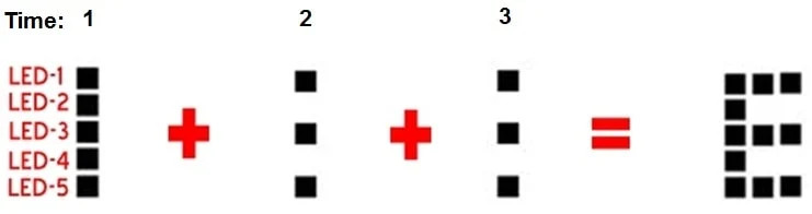
What is POV(Persistence of Vision)? It can be defined in simple words. When a person sees an object, its image remains in the retina of the eye for a time interval of 1/16th of a second. This phenomenon is known as persistence of vision. This phenomenon is used in the POV Display to form images. We turn the LEDs on and off in such a way that the different images overlap each other forming letters. For example:
1 2 3 <– Time
1 1 1 <– Bulb 1
1 0 0 <– Bulb 2
1 1 1 <– Bulb 3
1 0 0 <– Bulb 4
1 1 1 <– Bulb 5
Each row represents the 5 LEDs we use to make the Arduino POV display and each column is a time interval. Each element in the row represents the state of the LED at that given time.
At t = 1 Bulbs 1,2,3,4,5 are ON
At t = 2 Bulbs 1,3,5 are ON
This way we can visually see the letter E formed by the LEDs but the time interval would be very small in milliseconds. Due to the short time intervals and the ability of the LEDs to turn ON and OFF very quickly we can see the letter E as all the 3 images merge. As the motor is spinning and time passes, each LED moves from one position to the next, so all these images merge together.
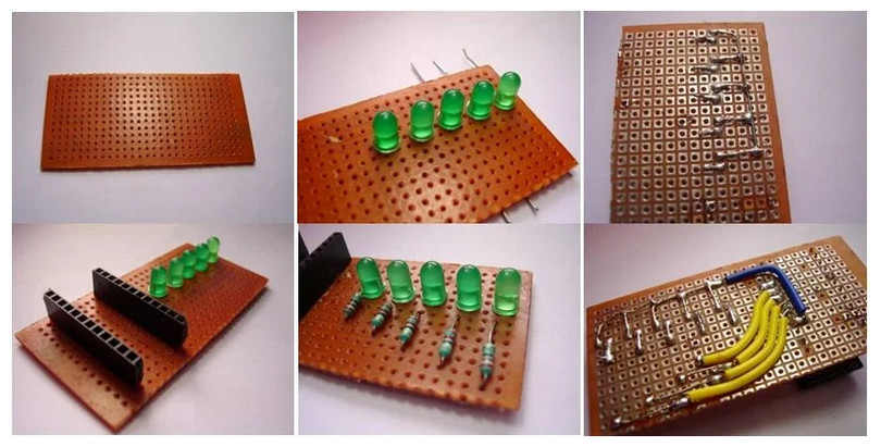
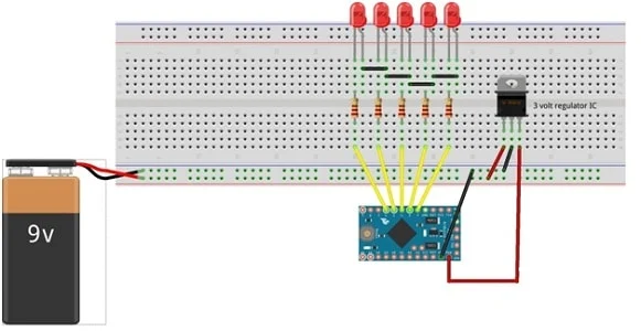
Cut the perf board to the appropriate size. Then connect the LEDs and solder it as shown in the figure below. Then connect the Arduino case (where Arduino is to be placed). Connect the resistors to the positive pins of the LEDs and connect the negative pins together. Then connect the LEDs to the Arduino. The first LED(on the upper side) connects to the Arduino pin 2. Connect the second LED to the Arduino 3rd pin. Connect all LEDs as shown in the circuit diagram. At last, connect a pin for mobile battery. For plug and play use, connect a switch. If you don’t have a mobile battery, you can also use a 9-volt battery. In this circuit, I have connected a 9-volt battery to the Arduino with a 3V regulator.
Assembling the Rotary Mechanism for the Arduino POV Display
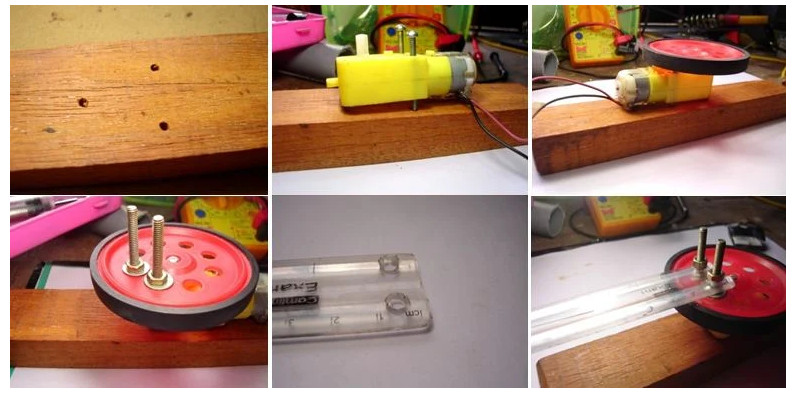
Drill and make holes on the wooden block to attach the motor and connect the motor as shown in the figure. Connect the wheel and screw the two bolts on the holes of the wheel. Then cut a half of the scale and drill two holes and attach the scale and screw it (the electronics part is going to be attached here).
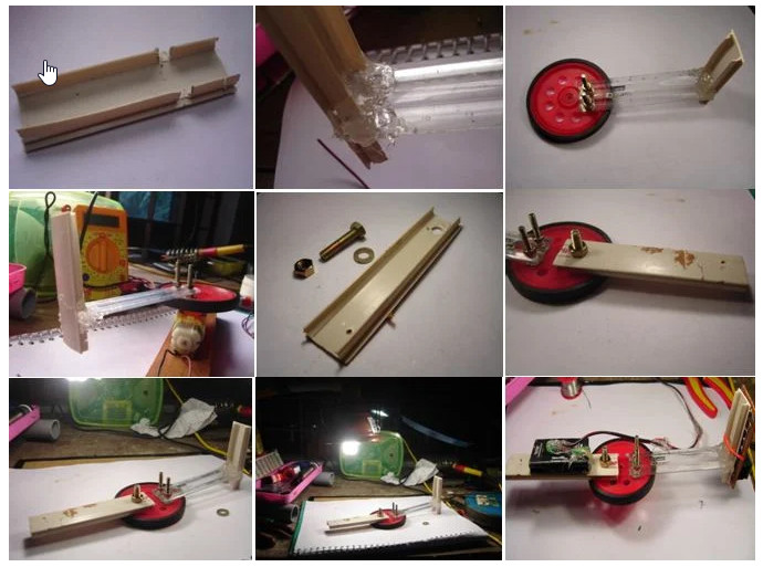
EnTake a small plastic piece (as shown in the figure above) and connect the plastic piece perpendicular to the scale using the glue gun. Then take another piece of plastic and screw it on the other side of the wheel. Then make the mobile battery pack by soldering extension wires to the terminals. Connect the electronic part (the display board with LEDs) to the perpendicular part and connect the battery to the other side. Balance and fix the wheel on the center (make the center of gravity the center of the wheel). This is for minimizing vibration when it rotates.
For my Arduino POV, I changed the Green LED to a Red LED because when I capture the video using a camera, the green color is not seen clearly. Green color scatters more than Red (red color has the highest wave length) and can only be captured using a camera with better Frames Per Second.
Now all you need to do is power up the module and the motor used to turn the whole system. And then you would be able to see “Hello World” lighting up when the motor reaches the correct rpm.
End Of Post