


BOM
IC1 & IC3= IC 4017(2pcs)
IC3= IC 555
5mm LEDs (81 pcs)
R1 to R9= 1K resistor(9pcs)
T1 to T9= 2N2222 transistor(9pcs)
R12= 3.3K resistor
C1= 2.2uF capacitor
P1= 100K potentiometer
D1= 1N4007 diode
R11= 10K resitor
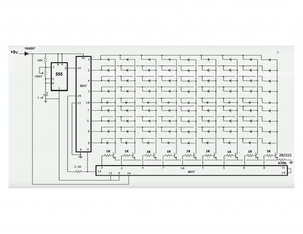
The circuit works off a 9V battery.
IC2 is wired in astable multivibrator mode. For clock frequency generation, 10µF capacitor (C1), resistor R20 and potmeter VR1 are used. VR1 is used to change the LEDs’ flashing rate. Frequency (f) can be calculated using the relationship:
f=1/(0.69(R20+2×VR1)×C1)
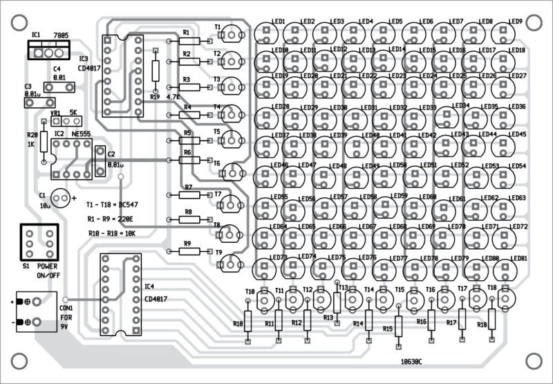
IC2 generates clock for the first decade counter (IC3). This counter controls the rows (anodes of LEDs) with the help of nine BC547 transistors (T1 through T9). These transistors can be controlled by output pins (O0 through O9) of IC3 along with 220-ohm resistors (R1 through R9) that are connected to collectors of T1 through T9 for current-limiting purpose.
Tenth output (O9) is fed to pin 14 (CLK) of CD4017 (IC4) as clock input. Columns of the LEDs can be controlled through collectors of BC547 BJT transistors (T10 through T18) that are connected to cathodes of LED columns. Outputs of IC4 are connected to bases of transistors T10 through T18 through resistors R10 through R18, respectively.
Clock rate can be varied with the help of 5-kilo-ohm potmeter (VR1) to produce stunning running lights effect based on the concept of persistence of vision.
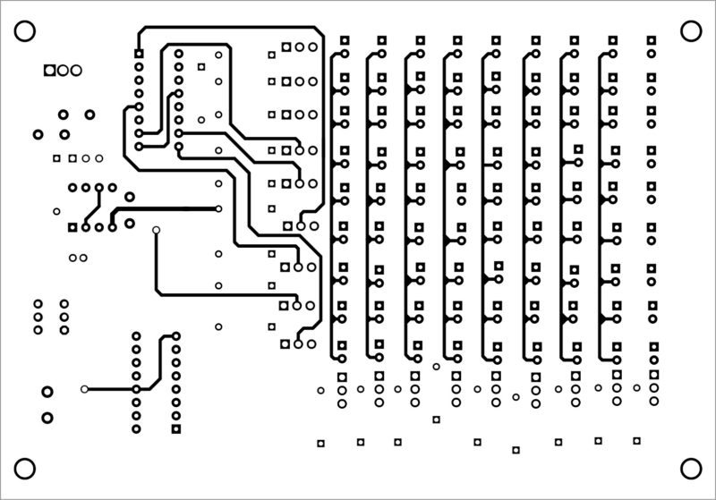
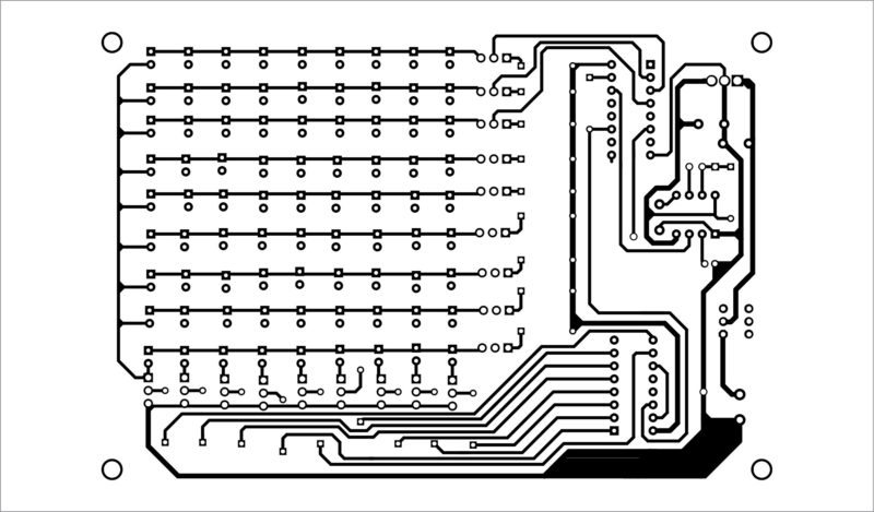
Construction and testing
Double-side PCB layouts for the 81-LED chaser light and their component layouts are shown in hereinafter figures, respectively. After assembling the circuit on the PCB, enclose it in a suitable plastic box.