
RIf you’ve dabbled with some beginner Arduino projects, but are looking for something a little permanent and on a whole other level of awesome, then the humble 4 x 4 x 4 LED cube is a natural choice. Construction is far easier than you might think, and using a multiplexing we can control all the LEDs directly from just a single Arduino Uno board.
You Will Need
- An Arduino. The code supplied assumes an Arduino Uno, but could be adjusted to a larger model too.
- 64 LEDs – the exact choice is up to you, but I used these superbright 3mm Blue LEDs (3.2v 30ma) @ £2.64 for 50.
- 16 Resistors of the appropriate value for your LEDs. For the LEDs above, 99 pence bought 100 of these. Use ledcalc.com – enter 5v for the supply voltage, the voltage of the LEDs (in my case 3.2) and the current in milliamps (3.2). Your desired resistor will be shown in the box labelled “Nearest higher rated resistor”, then just search for that value on eBay.
- Some craft wire to strengthen basic structure and for decoration – I used 0.8mm thickness.
- A prototyping board of some type that you can solder all your bits to. I used one which didn’t have full tracks along it as I don’t have a track cutter, but use whatever suits you. An Arduino prototyping shield is a little too small though, unless you really squeeze your LEDs together.
- Random component wire – some network cable strands and some of the prototyping wires from a kit will work fine.
- Crocodile clips or “helping hands” are useful for holding bits in place.
- Soldering iron, and solder.
- Some scrap wood.
- A drill, with the same size bit as your LEDs.
The Principle Of This Design
Before you begin construction, it’s important to have an complete overview of how this thing is going to work so you can improvise and identify errors as you go along. Some LED cubes use a single output pin for every single LED – however in a 4x4x4 cube, that would need 64 pins – which we certainly don’t have on an Arduino Uno. One solution would be to use shift registers, but this is unnecessarily complicated.
Shift registers
What Is A Shift Register?
An output shift register, technically speaking, receives data in serial and outputs it in parallel. In practical terms, this means we can quickly send a bunch of output commands to the chip, tell it to activate, and the outputs will be sent to the relevant pins. Instead of iterating through each pin, we simply send the output required to all the pins at once, as a single byte or more of information.
If it helps you to understand, you can think of a shift register as an ‘array’ of digital outputs, but we can skip the usual digitalWrite commands and simply send a series of bits to turn them on or off.
How Does It Work?
The shift register we will be using – the 74HC595N included in the Oomlout starter kit – needs only 3 control pins. The first is a clock – you needn’t worry too much about this as the Arduino serial libraries control it – but a clock is basically just an on/off electrical pulse that sets the pace for the data signal.
The latch pin is used to tell the shift register when it should turn its outputs on and off according to the bits we just sent it – i.e., latching them into place.
Finally, the data pin is where we sent the actual serial data with the bits to determine the on/off state of the shift register’s outputs.
The whole process can described in 4 steps:
- Set the data pin to high or low for the first output pin on the shift register.
- Pulse the clock to ‘shift’ the data into the register.
- Continue setting the data and pulsing the clock until you have set the required state for all output pins.
- Pulse the latch pin to activate the output sequence.
Implementation
You need the following components for this project:
- 7HC595N shift register chip
- 8 LEDS and appropriate resistors, or whatever you want to output to
- The usual breadboard, connectors, and a basic Arduino
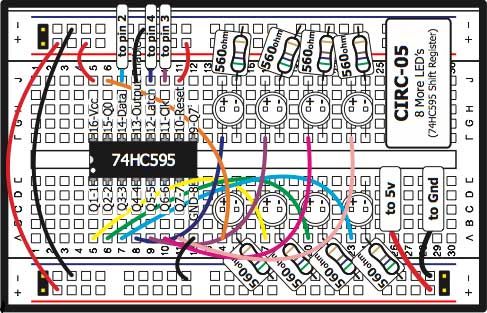
If you have the Oomlout starter kit, you can download the breadboard layout from here.
The board layout:
Daisy Chaining More Than One Shift Register
The remarkable thing about Shift Registers is that if they are given more than 8-bits of information (or however large their registry is), they will shift the other additional bits out again. This means you can connect up a series of them together, push in one long chain of bits, and have it distributed to each register separately, all with no additional coding on your part.
Although we won’t be detailing the process or schematics here, if you have more than one shift register you can try the project from the official Arduino site here.
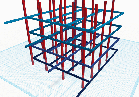
In order to control all those LEDs in just 20 pins, we’ll be using a technique called multiplexing. By breaking the cube down into 4 separate layers, we only need control pins for 16 LEDs – so to light a specific LED, we must activate both the layer, and the control pin, giving us a total requirement of 16+4 pins. Each layer has a common cathode – the negative part of the circuit – so all the negative legs are joined together, and connected to a single pin for that layer.
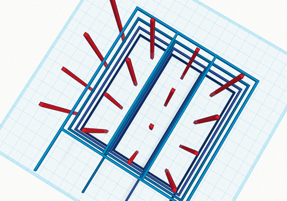
On the anode (positive) side, each LED will be connected to the corresponding LED in the layer above and below it. Essentially, we have 16 columns of the positive legs, and 4 layers of the negative. Here’s some 3D views of the connections to help you understand:
Construction
Since we won’t be using a full metal structure to solder to, we want all the legs of the LEDs to overlap by about a quarter and give rigidity to the structure. Fold the cathode of your LEDs – the side with the flat notch in the head and the shorter leg – over as shown in the diagram. (It doesn’t really matter if you bend it left or right, so long as you’re consistent and it never touches the anode)
The first critical part of this project is making a wooden jig. This will hold a layer of LEDs while you solder the legs together, so it needs to be accurate and not too loose. Using the same size drill bit as your LEDs, measure out and then drill a 4×4 matrix of equidistant holes. Bear in mind that you want about a quarter of the leg to overlap with its neighbour, and do use an actual ruler. Check each hole to ensure an LED can fit snugly , but not so tight that you won’t be able to get it out again, or you’ll have problems when trying to remove a fully soldered layer.
Solder the cathodes of 4 rows of LEDs. Be careful not to burn out the LEDs – you want a good hot iron, and to be in and out. Here’s my first four rows completed.
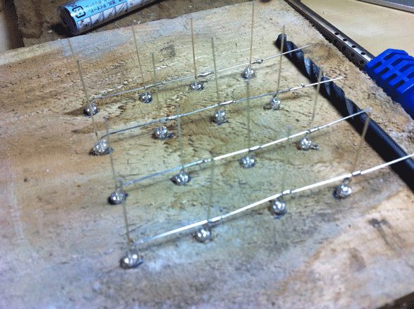
Now, to strengthen the rigidity of the layer, cut and solder two straight bits of craft wire to either end, making sure they connect with each row. This is your first layer complete. Leave all excess legs sticking out at the side for now.
Now would be a great time to test – just load up the default Arduino blink app, and with a resistor connected, put the ground to the layer frame, and press the positive lead to each LED in turn.
Don’t worry if your soldering isn’t perfect – as long it’s not going to break and the connection is solid, it won’t affect the final product. I admit, my soldering was pretty hopeless, my jig was off, and it all resembled the leaning tower of Pisa. Still, I’m proud of the finished cube, and when the LEDs are lit you aren’t going to be looking at the solder joints anyway!
Joining Layers
Once you have 4 completed layers, you’ll want to join all the vertical legs together. I found this to be the hardest part of the build, and to aid the process I cut a riser out of card.
1st Silly Mistake To Avoid
Only after completing a full layer did I realise my card riser was stuck in place, so I had to cut it out! Don’t make the same mistake I did – make the riser longer on the side, and join the pieces of card outside of the cube, so when you’ve completed the layer, you can deconstruct the riser and pull out the card.
2nd Silly Mistake To Avoid
Don’t solder the vertical leg to the cathode frame, obviously. Vertical legs should only connect to other vertical legs, and nothing else.
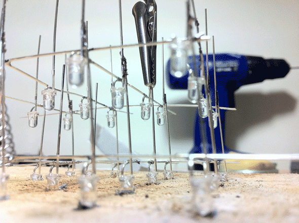
Again, test after each layer has been attached. Test all the layers, in fact, only touching the positive lead to the tip of the uppermost layer, thereby ensuring you’ve got good contact going through all layers.
When all 4 layers were soldered together, I set about cleaning up a bit – I left one single leg extended out of each layer in a kind of stepping stone fashion – this would be dropped down to the board later. Other extraneous bits of metal frame and legs were cut off. Obviously, don’t cut any of the vertical legs – we need to put these into our protoytping board.
Fixing To The Board
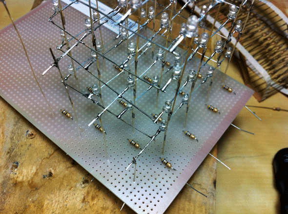
Remember when I said fixing each layer to itself was the hardest part? I lied. Trying to fit 16 LED legs into tiny holes on a prototyping board is actually harder. The easiest way I found was to poke through 4 at a time, secure them underneath with crocodile clips, then move on to the next row of 4. Use a marker pen to mark out spacing in advance if it helps.
In retrospect, I would have placed the resistors into the protoboard first, actually. As it is, I soldered all the legs of the cube into the board first, then tried to delicately squeeze resistors in between each one. Learn from my mistake, and place your resistors first.
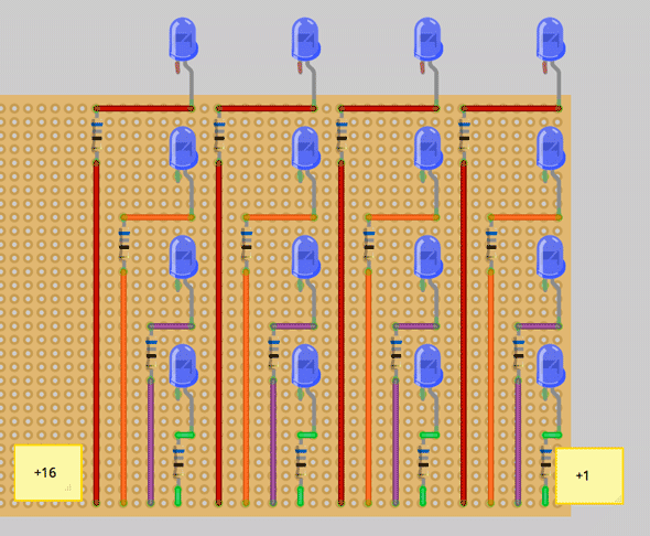
I tried to space them equally in a stepping fashion so then I could use one entire side of the cube for all the final connections to the Arduino. Here’s the circuit diagram I went with:
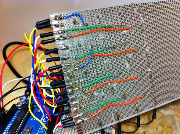
For the four negative layers, I dropped a single wire down from each layer, then just pulled them off to the side, like this:
Finally, I added some plug wires that I could then place into the relevant Arduino pins. Use the longest kind you have. Note I messed the order up in places due to poor planning. Each row of LEDs was colour coded though.
Programming Your Cube
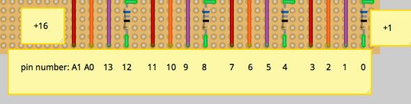
I know you can’t wait to get this thing fired up, so plug the 4 negative layers into Analog I/O ports A2 (bottom layer) through A5 (top layer) (these can also act as digital I/O). Then plug in the 16 LED control pins, starting with +1 on the far right to digital I/O port 0, with +15 and +16 going into analog A0 and A1. (Don’t use AREF and GND)
End Of Post