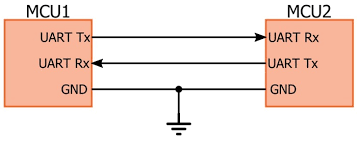
UART (Universal Asynchronous Transmitter Receiver), this is the most common protocol used for full duplex serial communication. It is a single LSI (large scale integration) chip designed to perform asynchronous communication. This device sends and receives data from one system to another system.
In this tutorial, you will learn the basics of UART communication, and working of the UART.
What is UART?
“UART” stands for Universal Asynchronous receiver-transmitter. It is a peripheral that is present inside a microcontroller. The function of UART is to convert the incoming and outgoing data into the serial binary stream. An 8-bit serial data received from the peripheral device is converted into the parallel form using serial to parallel conversion and parallel data received from the CPU is converted using serial to parallel conversion.
Why UART is used?
Protocols like SPI (serial peripheral interface) and USB (Universal Serial Bus) are used for fast communication. When high-speed data transfer is not required UART is used. It is a cheap communication device with a single transmitter/receiver. It requires a single wire for transmitting the data and another wire for receiving.
RS232 and UART
Logic levels represent the operating voltage levels that a device can withstand to operate in a safe zone. Here are the voltage levels for RS232 and TTL.
RS232 Logic:
RS232 Voltage Levels
| Logic Level | Voltage Range |
|---|---|
| Logic High or OFF output | -5V to -15V |
| Logic Low or ON output | +5V to +15V |
| Logic High or OFF input | -3V to -15V |
| Logic Low or ON input | +3V to +15V |
In most cases RS232 levels range from -12V to +12V. For instance, an ASCII value for a character ‘A‘ in RS232 is 65 and 41 in Hexadecimal. So in 8-bit binary format, it is 0100 0001. Here shows the representation of RS232 logic levels for ASCII ‘A‘.
End Of Post


